


This publication is Open Access under the license indicated. Learn More

ACS Editors' Choice® is a collection designed to feature scientific articles of broad public interest. Read the latest articles
Halometallurgy: Reduction of Battery Cathode Materials under a Quasi-Inert Environment of Alkali Chloride SaltsClick to copy article linkArticle link copied!
- Arseniy Bokov*Arseniy Bokov*Email: [email protected]Karlsruhe Institute of Technology (KIT), Institute for Applied Materials - Energy Storage Systems (IAM-ESS), Hermann-von-Helmholtz-Platz 1, Eggenstein-Leopoldshafen 76344, GermanyHelmholtz Institute Ulm for Electrochemical Energy Storage (HIU), Helmholtz Strasse 11, Ulm 89081, GermanyMore by Arseniy Bokov
- Anna ShelyugAnna ShelyugKarlsruhe Institute of Technology (KIT), Institute for Nuclear Waste Disposal (INE), Hermann-von-Helmholtz-Platz 1, Eggenstein-Leopoldshafen 76344, GermanyMore by Anna Shelyug
- Liuda MereacreLiuda MereacreKarlsruhe Institute of Technology (KIT), Institute for Applied Materials - Energy Storage Systems (IAM-ESS), Hermann-von-Helmholtz-Platz 1, Eggenstein-Leopoldshafen 76344, GermanyMore by Liuda Mereacre
- Michael KnappMichael KnappKarlsruhe Institute of Technology (KIT), Institute for Applied Materials - Energy Storage Systems (IAM-ESS), Hermann-von-Helmholtz-Platz 1, Eggenstein-Leopoldshafen 76344, GermanyMore by Michael Knapp
- Helmut EhrenbergHelmut EhrenbergKarlsruhe Institute of Technology (KIT), Institute for Applied Materials - Energy Storage Systems (IAM-ESS), Hermann-von-Helmholtz-Platz 1, Eggenstein-Leopoldshafen 76344, GermanyHelmholtz Institute Ulm for Electrochemical Energy Storage (HIU), Helmholtz Strasse 11, Ulm 89081, GermanyMore by Helmut Ehrenberg
Chemistry of Materials
Copyright © 2026 The Authors. Published by American Chemical Society. This publication is licensed under
License Summary*
You are free to share (copy and redistribute) this article in any medium or format and to adapt (remix, transform, and build upon) the material for any purpose, even commercially within the parameters below:

Creative Commons (CC): This is a Creative Commons license.

Attribution (BY): Credit must be given to the creator.
*Disclaimer
This summary highlights only some of the key features and terms of the actual license. It is not a license and has no legal value. Carefully review the actual license before using these materials.
Abstract
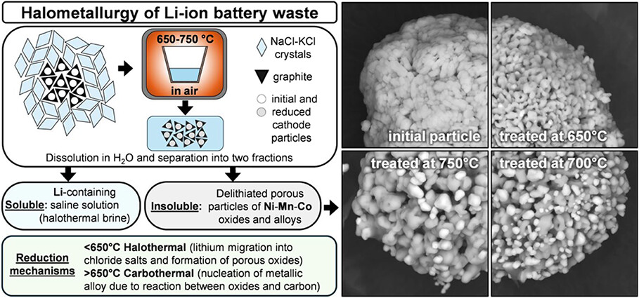
This study introduces halometallurgy, an approach for reducing common Li-ion cathode materials in air using a eutectic mixture of chloride salts, with direct implications for processing battery black mass containing NMC, NCA, LCO, LNMO, and LMO. In-depth analysis, including in situ XRD, SEM/EDX, and TGA-DSC, reveals that reduction in the presence of NaCl-KCl proceeds via distinct halothermal and carbothermal routes. During the halothermal stage, lithium migrates from cathode particles into the chlorides, leading to the decomposition of layered or spinel structures into a solid solution of cubic oxides. Lithium migration facilitates the melting of the salts, resulting in the encapsulation of the oxide phase and the creation of quasi-inert conditions. This enables further reduction during the carbothermal stage and promotes the nucleation of metallic crystallites. Upon washing with water, lithium predominantly remains in the saline solution, termed halothermal brine, while the insoluble fraction consists of porous transition metal oxides and graphite. Depending on cathode composition, halothermal reduction is observed at 460–640 °C, while carbothermal reduction occurs above 620–650 °C. Typical black-mass impurities, including current collectors, binders, and electrolyte residues, were also examined, demonstrating relevance for real waste streams. The proposed treatment offers a pathway toward decentralized battery recycling.
This publication is licensed under
License Summary*
You are free to share(copy and redistribute) this article in any medium or format and to adapt(remix, transform, and build upon) the material for any purpose, even commercially within the parameters below:
Creative Commons (CC): This is a Creative Commons license.
Attribution (BY): Credit must be given to the creator.
*Disclaimer
This summary highlights only some of the key features and terms of the actual license. It is not a license and has no legal value. Carefully review the actual license before using these materials.
1. Introduction
2. Materials and Methods
3. Results and Discussion
Figure 1
Figure 1. SEM images of NMC samples before (a-c) and after (d-f) heating to 670 °C with Gr and NaCl-KCl. Images are arranged for side-by-side comparison at the same magnification between (a,d), (b,e), and (c,f) to highlight changes in particle morphology, pellet microstructure, and the interfacial region.
Figure 2
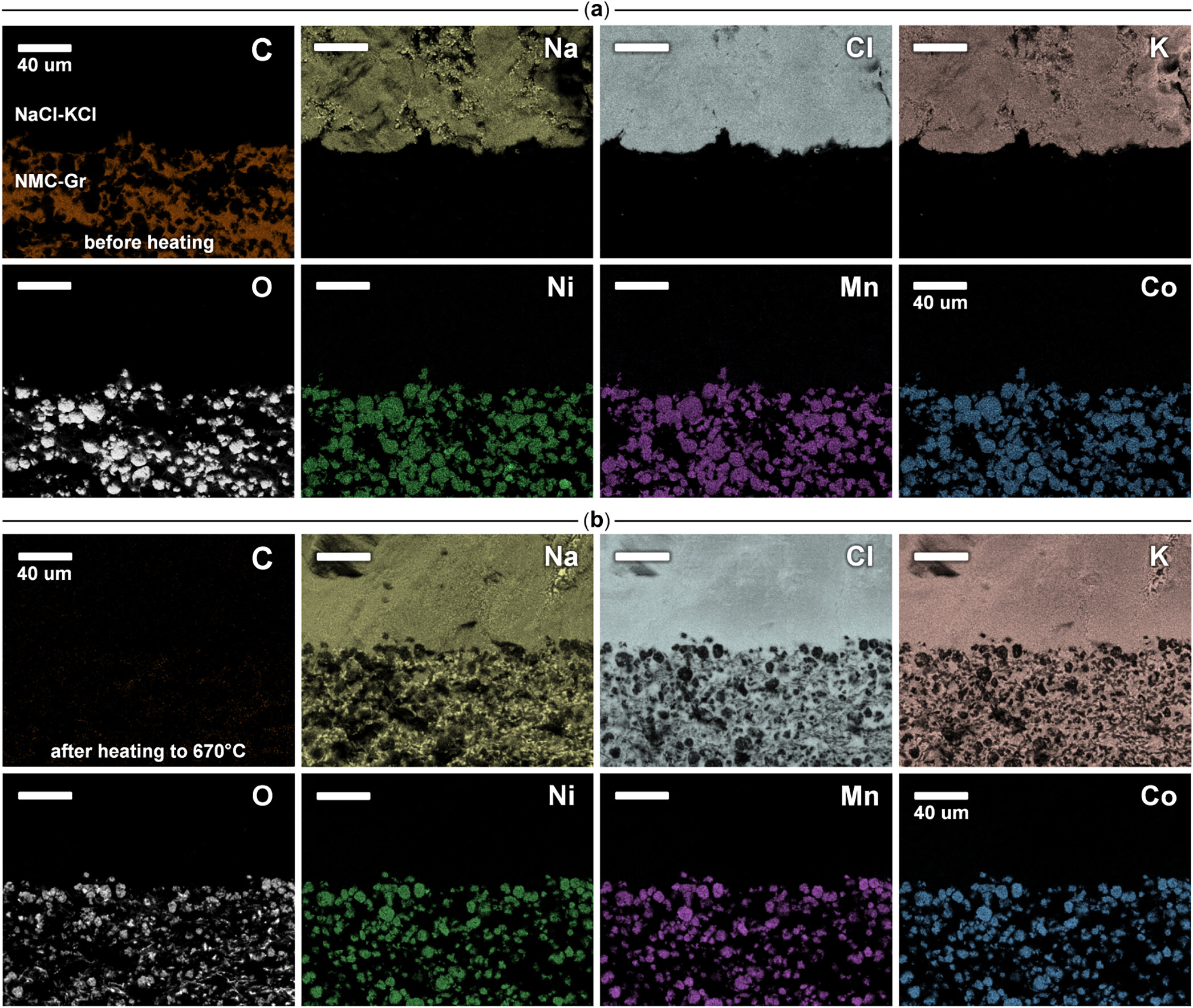
Figure 2. EDX elemental mapping of the interfacial regions between NMC-Gr and NaCl-KCl before (a) and after heating to 670 °C (b). Elements are shown in the order: C, Na, Cl, K, O, Ni, Mn, Co.
Figure 3
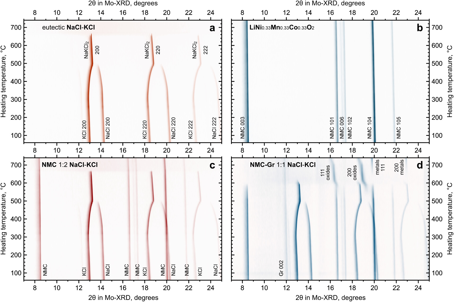
Figure 3. In situ XRD during heating of model material systems: NaCl-KCl eutectic only (a), LiNi0.33Mn0.33Co0.33O2 only (b), mixture of NMC and NaCl-KCl at a 1:2 mass ratio (c), mixture of NMC-Gr and NaCl-KCl at a 1:1 mass ratio (d).
Figure 4
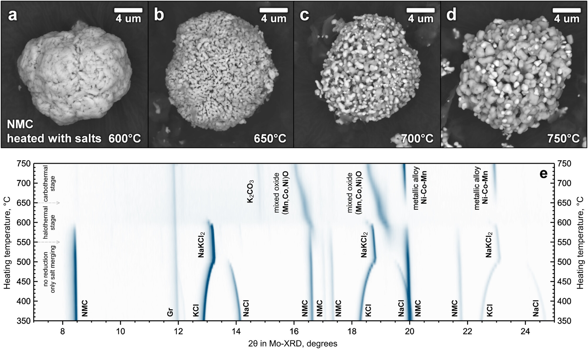
Figure 4. SEM images of ex situ NMC samples and corresponding in situ XRD data. Particle morphology after heat treatment with NaCl-KCl salts at 600 °C (a), 650 °C (b), 700 °C (c), and 750 °C (d), together with the diffraction patterns recorded during heating in the 350–750 °C range (e).
Figure 5
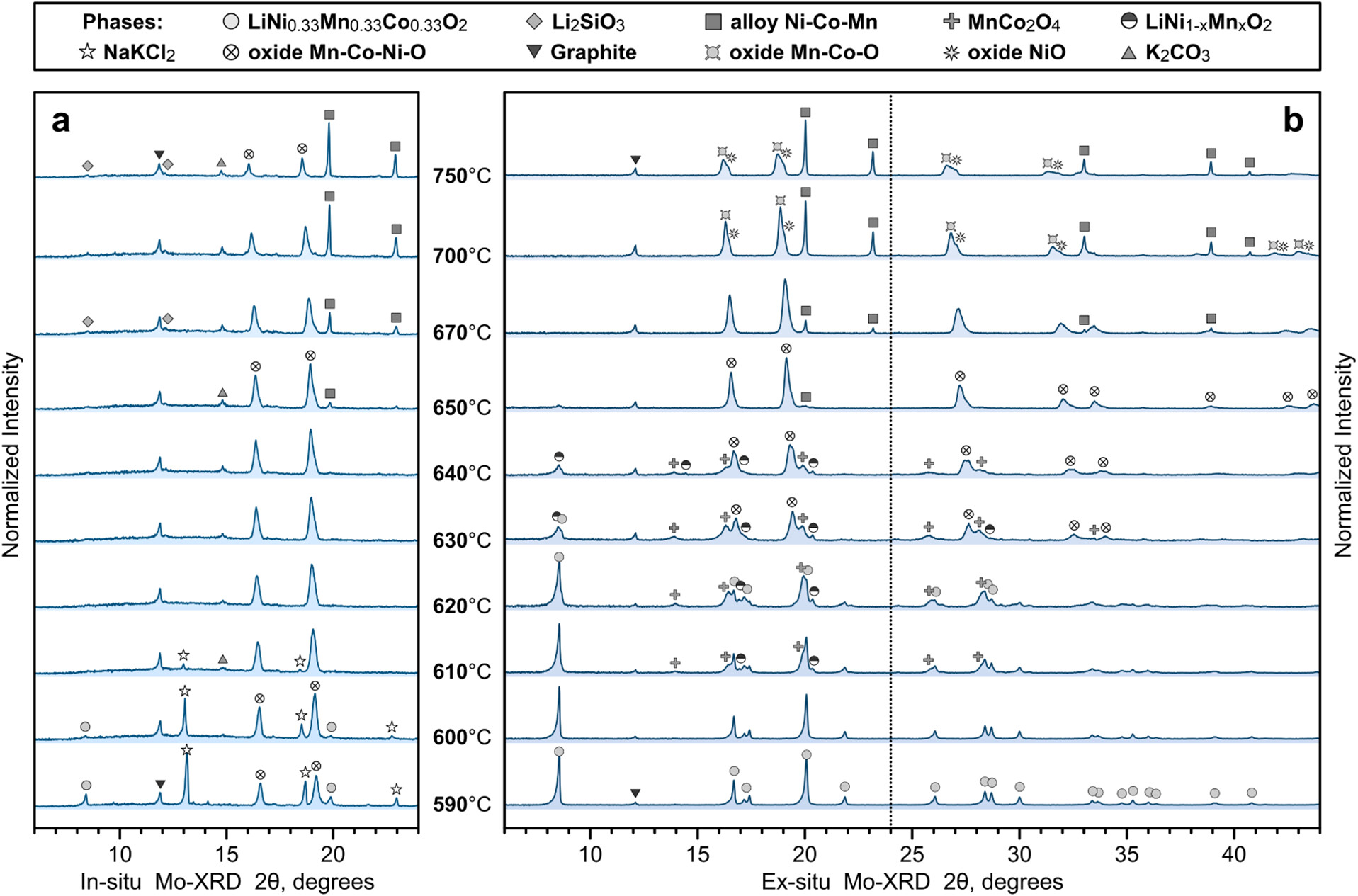
Figure 5. Comparison of in situ and ex situ XRD for NMC-Gr with NaCl-KCl: patterns at high temperatures in quartz capillaries (a) and room-temperature scans after washing of samples annealed in alumina crucibles (b). The dashed line in the ex situ patterns indicates the corresponding range of the in situ scans.
Figure 6
Figure 6. Effect of lithium migration on the behavior of chloride salts. TGA-DSC for different mass ratios of NMC-Gr to NaCl-KCl (a, b), in situ XRD during cooling of a sample with a 1:1 ratio and a model ternary chloride system (c, d), and EDX elemental mapping of solidified salt containing a reduced particle after heat treatment at 670 °C (e).
Figure 7
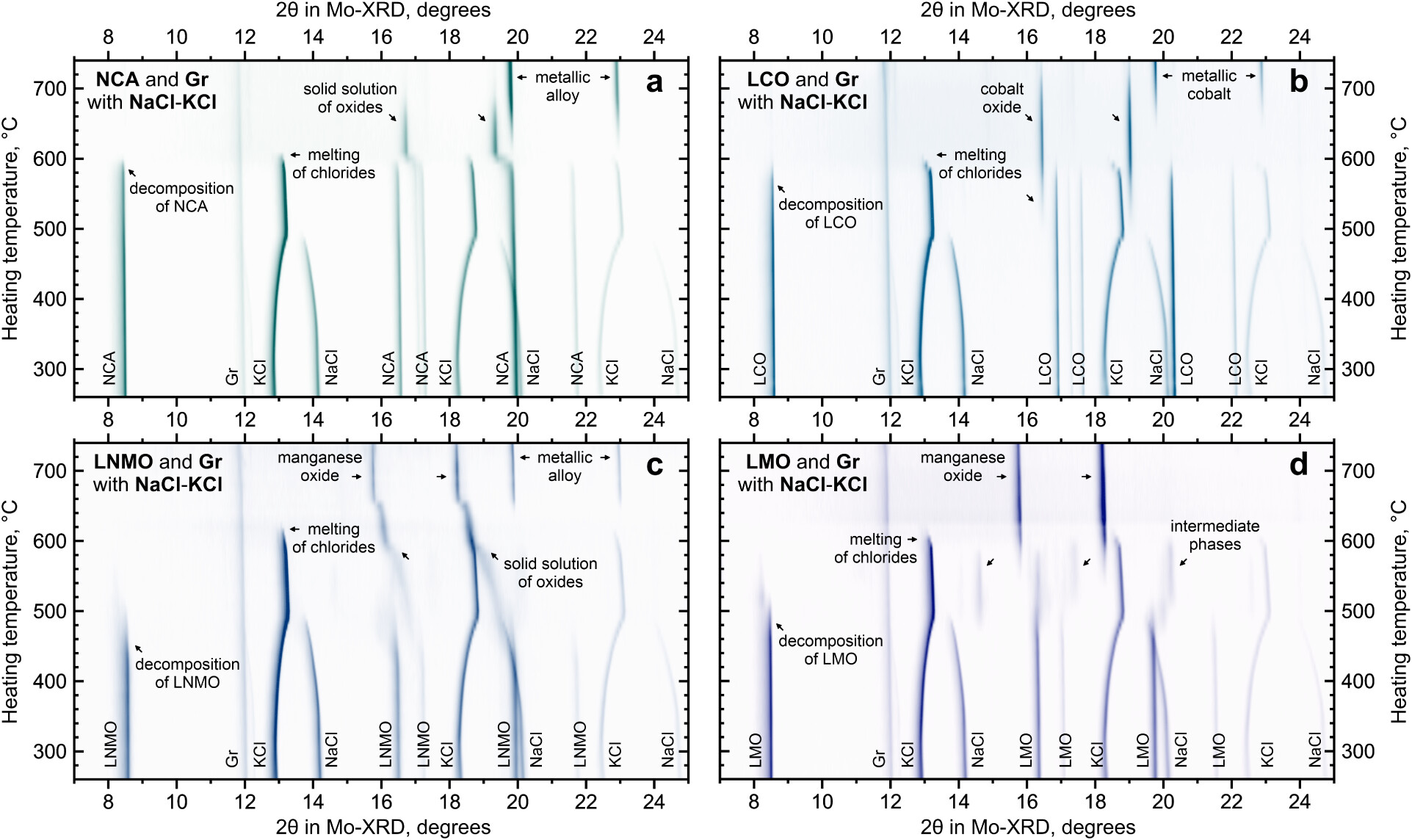
Figure 7. In situ XRD during heating of common cathode materials mixed with graphite and NaCl-KCl salts: LiNi0.80Co0.15Al0.05O2 (a), LiCoO2 (b), LiNi0.5Mn1.5O4 (c), and LiMn2O4 (d).
Figure 8
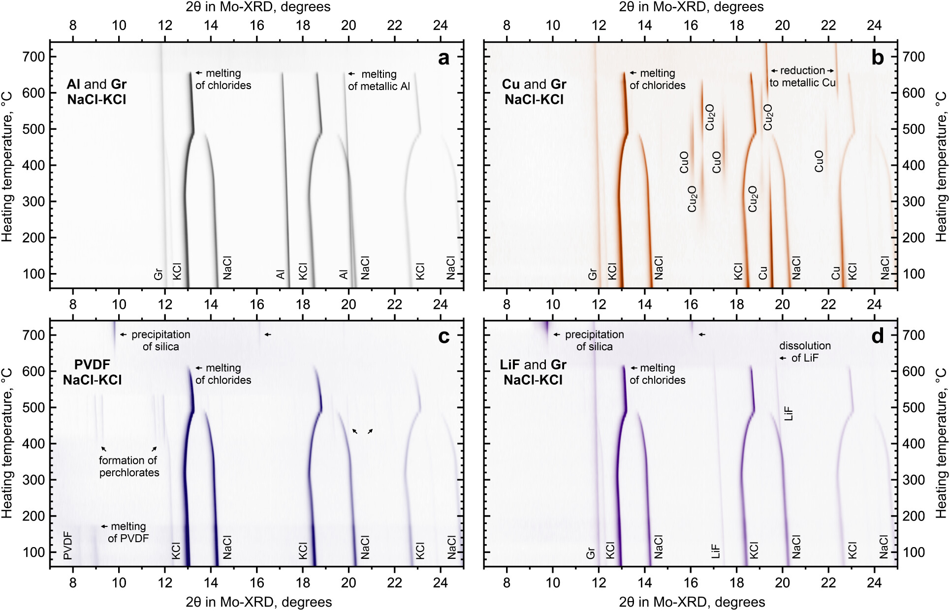
Figure 8. In situ XRD during heating of typical black-mass impurities mixed with NaCl-KCl: Al (a) and Cu (b) current collectors with graphite, PVDF binder (c), and LiF with graphite (d).
Figure 9
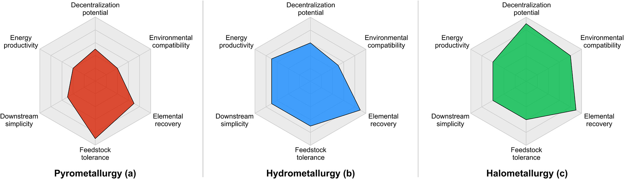
Figure 9. Radar diagrams for techno-economic comparison of battery recycling routes: pyrometallurgy (a), hydrometallurgy (b), and halometallurgy (c). Radial axes increase from the center (low) to the edge (high), indicating the relative levels of each parameter.
4. Conclusions
Supporting Information
The Supporting Information is available free of charge at https://pubs.acs.org/doi/10.1021/acs.chemmater.5c02896.
It includes XRD patterns for starting materials (Figure S1), details of the in situ XRD experimental setup (Figure S2), and optical microscopy of NMC-Gr together with SEM images of particle morphology after the heat treatment with NaCl-KCl (Figures S3, S4). The in situ XRD data are presented for NMC622-Gr with salts (Figure S5), equimolar NMC-Gr under nitrogen without salts (Figure S6), LiPF6 and LFP-Gr (Figure S9), as well as Al/Cu impurities with Gr and NaCl-KCl (Figure S11). Additional characterization of chloride salts during cooling and after solidification is provided by in situ XRD and EDX (Figures S7, S8), together with ICP-OES results for insoluble and soluble fractions (Figure S10, Table S1). Finally, the relevance of halometallurgy for industrial black mass is demonstrated through XRD, DSC, and optical microscopy (Figures S12, S13, S14) (PDF)
Terms & Conditions
Most electronic Supporting Information files are available without a subscription to ACS Web Editions. Such files may be downloaded by article for research use (if there is a public use license linked to the relevant article, that license may permit other uses). Permission may be obtained from ACS for other uses through requests via the RightsLink permission system: http://pubs.acs.org/page/copyright/permissions.html.
Author Information
- Arseniy Bokov - Karlsruhe Institute of Technology (KIT), Institute for Applied Materials - Energy Storage Systems (IAM-ESS), Hermann-von-Helmholtz-Platz 1, Eggenstein-Leopoldshafen 76344, Germany; Helmholtz Institute Ulm for Electrochemical Energy Storage (HIU), Helmholtz Strasse 11, Ulm 89081, Germany;
 https://orcid.org/0000-0002-0293-8225;
- Anna Shelyug - Karlsruhe Institute of Technology (KIT), Institute for Nuclear Waste Disposal (INE), Hermann-von-Helmholtz-Platz 1, Eggenstein-Leopoldshafen 76344, Germany;https://orcid.org/0000-0003-3233-1632
- Michael Knapp - Karlsruhe Institute of Technology (KIT), Institute for Applied Materials - Energy Storage Systems (IAM-ESS), Hermann-von-Helmholtz-Platz 1, Eggenstein-Leopoldshafen 76344, Germany;https://orcid.org/0000-0003-0091-8463
- Helmut Ehrenberg - Karlsruhe Institute of Technology (KIT), Institute for Applied Materials - Energy Storage Systems (IAM-ESS), Hermann-von-Helmholtz-Platz 1, Eggenstein-Leopoldshafen 76344, Germany; Helmholtz Institute Ulm for Electrochemical Energy Storage (HIU), Helmholtz Strasse 11, Ulm 89081, Germany;https://orcid.org/0000-0002-5134-7130
Acknowledgments
This study was conducted as part of the research activities within CELEST (Center for Electrochemical Energy Storage Ulm-Karlsruhe). The authors are thankful to Michaela Nagel for assistance with optical microscopy and to Stephanie Kraft for ICP-OES measurements.
References
This article references 70 other publications.
- 1Maisel, F.; Neef, C.; Marscheider-Weidemann, F.; Nissen, N. F. A Forecast on Future Raw Material Demand and Recycling Potential of Lithium-Ion Batteries in Electric Vehicles. Resour. Conserv. Recycl. 2023, 192, 106920, DOI: 10.1016/j.resconrec.2023.106920Google ScholarThere is no corresponding record for this reference.
- 2Miao, Y.; Liu, L.; Zhang, Y.; Tan, Q.; Li, J. An Overview of Global Power Lithium-Ion Batteries and Associated Critical Metal Recycling. J. Hazard. Mater. 2022, 425, 127900, DOI: 10.1016/j.jhazmat.2021.127900Google ScholarThere is no corresponding record for this reference.
- 3Dunn, J.; Slattery, M.; Kendall, A.; Ambrose, H.; Shen, S. Circularity of Lithium-Ion Battery Materials in Electric Vehicles. Environ. Sci. Technol. 2021, 55 (8), 5189– 5198, DOI: 10.1021/acs.est.0c07030Google ScholarThere is no corresponding record for this reference.
- 4Gaines, L.; Richa, K.; Spangenberger, J. Key Issues for Li-Ion Battery Recycling. MRS Energy Sustainability 2018, 5 (1), 12, DOI: 10.1557/mre.2018.13Google ScholarThere is no corresponding record for this reference.
- 5Malik, M.; Chan, K. H.; Azimi, G. Review on the Synthesis of LiNixMnyCo1-x-yO2 (NMC) Cathodes for Lithium-Ion Batteries. Mater. Today Energy 2022, 28, 101066, DOI: 10.1016/j.mtener.2022.101066Google ScholarThere is no corresponding record for this reference.
- 6Purwanto, A.; Yudha, C. S.; Ubaidillah, U.; Widiyandari, H.; Ogi, T.; Haerudin, H. NCA Cathode Material: Synthesis Methods and Performance Enhancement Efforts. Mater. Res. Express 2018, 5 (12), 122001, DOI: 10.1088/2053-1591/aae167Google ScholarThere is no corresponding record for this reference.
- 7Liang, G.; Peterson, V. K.; See, K. W.; Guo, Z.; Pang, W. K. Developing High-Voltage Spinel LiNi0.5Mn1.5O4 Cathodes for High-Energy-Density Lithium-Ion Batteries: Current Achievements and Future Prospects. J. Mater. Chem. A 2020, 8 (31), 15373– 15398, DOI: 10.1039/D0TA02812FGoogle ScholarThere is no corresponding record for this reference.
- 8Lyu, Y.; Wu, X.; Wang, K.; Feng, Z.; Cheng, T.; Liu, Y.; Wang, M.; Chen, R.; Xu, L.; Zhou, J.; Lu, Y.; Guo, B. An Overview on the Advances of LiCoO2 Cathodes for Lithium-Ion Batteries. Adv. Energy Mater. 2021, 11 (2), 1– 29, DOI: 10.1002/aenm.202000982Google ScholarThere is no corresponding record for this reference.
- 9Bianchini, M.; Roca-Ayats, M.; Hartmann, P.; Brezesinski, T.; Janek, J. There and Back Again─The Journey of LiNiO2 as a Cathode Active Material. Angew. Chemie Int. Ed. 2019, 58 (31), 10434– 10458, DOI: 10.1002/anie.201812472Google ScholarThere is no corresponding record for this reference.
- 10Huang, Y.; Dong, Y.; Li, S.; Lee, J.; Wang, C.; Zhu, Z.; Xue, W.; Li, Y.; Li, J. Lithium Manganese Spinel Cathodes for Lithium-Ion Batteries. Adv. Energy Mater. 2021, 11 (2), 1– 21, DOI: 10.1002/aenm.202000997Google ScholarThere is no corresponding record for this reference.
- 11Bhar, M.; Ghosh, S.; Krishnamurthy, S.; Kaliprasad, Y.; Martha, S. K. A Review on Spent Lithium-Ion Battery Recycling: From Collection to Black Mass Recovery. RSC Sustainability 2023, 1 (5), 1150– 1167, DOI: 10.1039/D3SU00086AGoogle ScholarThere is no corresponding record for this reference.
- 12Donnelly, L.; Pirrie, D.; Power, M.; Corfe, I.; Kuva, J.; Lukkari, S.; Lahaye, Y.; Liu, X.; Dehaine, Q.; Jolis, E. M.; Butcher, A. The Recycling of End-of-Life Lithium-Ion Batteries and the Phase Characterisation of Black Mass. Recycling 2023, 8 (4), 59, DOI: 10.3390/recycling8040059Google ScholarThere is no corresponding record for this reference.
- 13Vanderbruggen, A.; Gugala, E.; Blannin, R.; Bachmann, K.; Serna-Guerrero, R.; Rudolph, M. Automated Mineralogy as a Novel Approach for the Compositional and Textural Characterization of Spent Lithium-Ion Batteries. Miner. Eng. 2021, 169, 106924, DOI: 10.1016/j.mineng.2021.106924Google ScholarThere is no corresponding record for this reference.
- 14Jung, J. C.-Y.; Sui, P.-C.; Zhang, J. A Review of Recycling Spent Lithium-Ion Battery Cathode Materials Using Hydrometallurgical Treatments. J. Energy Storage 2021, 35, 102217, DOI: 10.1016/j.est.2020.102217Google ScholarThere is no corresponding record for this reference.
- 15Makuza, B.; Tian, Q.; Guo, X.; Chattopadhyay, K.; Yu, D. Pyrometallurgical Options for Recycling Spent Lithium-Ion Batteries: A Comprehensive Review. J. Power Sources 2021, 491, 229622, DOI: 10.1016/j.jpowsour.2021.229622Google ScholarThere is no corresponding record for this reference.
- 16Neumann, J.; Petranikova, M.; Meeus, M.; Gamarra, J. D.; Younesi, R.; Winter, M.; Nowak, S. Recycling of Lithium-Ion Batteries─Current State of the Art, Circular Economy, and Next Generation Recycling. Adv. Energy Mater. 2022, 12 (17), 2102917, DOI: 10.1002/aenm.202102917Google ScholarThere is no corresponding record for this reference.
- 17Liang, Z.; Cai, C.; Peng, G.; Hu, J.; Hou, H.; Liu, B.; Liang, S.; Xiao, K.; Yuan, S.; Yang, J. Hydrometallurgical Recovery of Spent Lithium Ion Batteries: Environmental Strategies and Sustainability Evaluation. ACS Sustainable Chem. Eng. 2021, 9 (17), 5750– 5767, DOI: 10.1021/acssuschemeng.1c00942Google ScholarThere is no corresponding record for this reference.
- 18Davis, K.; Demopoulos, G. P. Hydrometallurgical Recycling Technologies for NMC Li-Ion Battery Cathodes: Current Industrial Practice and New R&D Trends. RSC Sustainable 2023, 1 (8), 1932– 1951, DOI: 10.1039/D3SU00142CGoogle ScholarThere is no corresponding record for this reference.
- 19Lombardo, G.; Ebin, B.; Foreman, M. R. S. J.; Petranikova, B.-M.; Petranikova, M. Chemical Transformations in Li-Ion Battery Electrode Materials by Carbothermic Reduction. ACS Sustainable Chem. Eng. 2019, 7 (16), 13668– 13679, DOI: 10.1021/acssuschemeng.8b06540Google ScholarThere is no corresponding record for this reference.
- 20Fu, Y.; He, Y.; Li, J.; Qu, L.; Yang, Y.; Guo, X.; Xie, W. Improved Hydrometallurgical Extraction of Valuable Metals from Spent Lithium-Ion Batteries via a Closed-Loop Process. J. Alloys Compd. 2020, 847, 156489, DOI: 10.1016/j.jallcom.2020.156489Google ScholarThere is no corresponding record for this reference.
- 21Zhu, X.; Li, Y.; Gong, M.; Mo, R.; Luo, S.; Yan, X.; Yang, S. Recycling Valuable Metals from Spent Lithium-Ion Batteries Using Carbothermal Shock Method. Angew. Chem. 2023, 135 (15), e202300074 DOI: 10.1002/ange.202300074Google ScholarThere is no corresponding record for this reference.
- 22Zhang, J.; Liang, G.; Yang, C.; Hu, J.; Chen, Y.; Wang, C. A Breakthrough Method for the Recycling of Spent Lithium-Ion Batteries without Pre-Sorting. Green Chem. 2021, 23 (21), 8434– 8440, DOI: 10.1039/D1GC02132JGoogle ScholarThere is no corresponding record for this reference.
- 23Stallmeister, C.; Friedrich, B. Influence of Flow-Gas Composition on Reaction Products of Thermally Treated NMC Battery Black Mass. Metals 2023, 13 (5), 923, DOI: 10.3390/met13050923Google ScholarThere is no corresponding record for this reference.
- 24Stallmeister, C.; Friedrich, B. Holistic Investigation of the Inert Thermal Treatment of Industrially Shredded NMC 622 Lithium-Ion Batteries and Its Influence on Selective Lithium Recovery by Water Leaching. Metals 2023, 13 (12), 2000, DOI: 10.3390/met13122000Google ScholarThere is no corresponding record for this reference.
- 25Lombardo, G.; Ebin, B.; Steenari, B.-M.; Alemrajabi, M.; Karlsson, I.; Petranikova, M. Comparison of the Effects of Incineration, Vacuum Pyrolysis and Dynamic Pyrolysis on the Composition of NMC-Lithium Battery Cathode-Material Production Scraps and Separation of the Current Collector. Resour. Conserv. Recycl. 2021, 164, 105142, DOI: 10.1016/j.resconrec.2020.105142Google ScholarThere is no corresponding record for this reference.
- 26Dash, A.; Vaßen, R.; Guillon, O.; Gonzalez-Julian, J. Molten Salt Shielded Synthesis of Oxidation Prone Materials in Air. Nat. Mater. 2019, 18 (5), 465– 470, DOI: 10.1038/s41563-019-0328-1Google ScholarThere is no corresponding record for this reference.
- 27Dash, A.; Sohn, Y. J.; Vaßen, R.; Guillon, O.; Gonzalez-Julian, J. Synthesis of Ti3SiC2 MAX Phase Powder by a Molten Salt Shielded Synthesis (MS3) Method in Air. J. Eur. Ceram. Soc. 2019, 39 (13), 3651– 3659, DOI: 10.1016/j.jeurceramsoc.2019.05.011Google ScholarThere is no corresponding record for this reference.
- 28Roy, C.; Banerjee, P.; Bhattacharyya, S. Molten Salt Shielded Synthesis (MS3) of Ti2AlN and V2AlC MAX Phase Powders in Open Air. J. Eur. Ceram. Soc. 2020, 40 (3), 923– 929, DOI: 10.1016/j.jeurceramsoc.2019.10.020Google ScholarThere is no corresponding record for this reference.
- 29Vanderbruggen, A.; Hayagan, N.; Bachmann, K.; Ferreira, A.; Werner, D.; Horn, D.; Peuker, U.; Serna-Guerrero, R.; Rudolph, M. Lithium-Ion Battery Recycling─Influence of Recycling Processes on Component Liberation and Flotation Separation Efficiency. ACS EST Eng. 2022, 2 (11), 2130– 2141, DOI: 10.1021/acsestengg.2c00177Google ScholarThere is no corresponding record for this reference.
- 30Babanejad, S.; Ahmed, H.; Andersson, C.; Samuelsson, C.; Lennartsson, A.; Hall, B.; Arnerlöf, L. High-Temperature Behavior of Spent Li-Ion Battery Black Mass in Inert Atmosphere. J. Sustainable Metall. 2022, 8 (1), 566– 581, DOI: 10.1007/s40831-022-00514-yGoogle ScholarThere is no corresponding record for this reference.
- 31Wei, X.; Guo, Z.; Zhao, Y.; Sun, Y.; Hankin, A.; Titirici, M. Recovery of Graphite from Industrial Lithium-Ion Battery Black Mass. RSC Sustainable 2025, 3 (1), 264– 274, DOI: 10.1039/D4SU00427BGoogle ScholarThere is no corresponding record for this reference.
- 32Zanoletti, A.; Cornelio, A.; Borgese, L.; Siviero, G.; Cinosi, A.; Galli, E.; Bontempi, E. Sample Preparation Procedures for Elemental Analysis of Critical Raw Materials in Lithium-Ion Battery Black Mass: Challenges Responding to the Supplementary Battery Recycling Regulation. J. Environ. Manage. 2025, 380, 124973, DOI: 10.1016/j.jenvman.2025.124973Google ScholarThere is no corresponding record for this reference.
- 33Sergeev, D.; Kobertz, D.; Müller, M. Thermodynamics of the NaCl–KCl System. Thermochim. Acta 2015, 606, 25– 33, DOI: 10.1016/j.tca.2015.03.003Google ScholarThere is no corresponding record for this reference.
- 34Anwar, J.; Leitold, C.; Peters, B. Solid–solid Phase Equilibria in the NaCl–KCl System. J. Chem. Phys. 2020, 152 (14), 144109, DOI: 10.1063/5.0003224Google ScholarThere is no corresponding record for this reference.
- 35Pritzl, D.; Teufl, T.; Freiberg, A. T. S.; Strehle, B.; Sicklinger, J.; Sommer, H.; Hartmann, P.; Gasteiger, H. A. Washing of Nickel-Rich Cathode Materials for Lithium-Ion Batteries: Towards a Mechanistic Understanding. J. Electrochem. Soc. 2019, 166 (16), A4056– A4066, DOI: 10.1149/2.1351915jesGoogle ScholarThere is no corresponding record for this reference.
- 36Chen, H.; Mattsson, A.-M.; King, L.; Liu, H.; Nielsen, I.; Ericson, T.; Preobrajenski, A.; Brant, W. R.; Hahlin, M. Study of Degradation Mechanisms in Aqueous-Processed Ni-Rich Cathodes for Enhanced Sustainability of Batteries. J. Mater. Chem. A 2024, 12 (37), 25393– 25406, DOI: 10.1039/D4TA03592EGoogle ScholarThere is no corresponding record for this reference.
- 37Sasaki, S.; Fujino, K.; Takeuchi, Y. X-Ray Determination of Electron-Density Distributions in Oxides, MgO, MnO, CoO, and NiO, and Atomic Scattering Factors of Their Constituent Atoms. Proc. Jpn. Acad., Ser. B 1979, 55 (2), 43– 48, DOI: 10.2183/pjab.55.43Google ScholarThere is no corresponding record for this reference.
- 38Zheng, Y.; Shao, P.; Yang, L.; Huang, Y.; Zhang, H.; Fang, L.; Qiu, C.; Tang, H.; Shao, J.; Luo, X. Gas Exchange-Driven Carbothermal Reduction for Simultaneous Lithium Extraction from Anode and Cathode Scraps. Resour. Conserv. Recycl. 2023, 188, 106696, DOI: 10.1016/j.resconrec.2022.106696Google ScholarThere is no corresponding record for this reference.
- 39Yan, Z.; Sattar, A.; Li, Z. Priority Lithium Recovery from Spent Li-Ion Batteries via Carbothermal Reduction with Water Leaching. Resour. Conserv. Recycl. 2023, 192, 106937, DOI: 10.1016/j.resconrec.2023.106937Google ScholarThere is no corresponding record for this reference.
- 40Konar, S.; Häusserman, U.; Svensson, G. Intercalation Compounds from LiH and Graphite: Relative Stability of Metastable Stages and Thermodynamic Stability of Dilute Stage I D. Chem. Mater. 2015, 27 (7), 2566– 2575, DOI: 10.1021/acs.chemmater.5b00235Google ScholarThere is no corresponding record for this reference.
- 41Oka, H.; Makimura, Y.; Uyama, T.; Nonaka, T.; Kondo, Y.; Okuda, C. Changes in the Stage Structure of Li-Intercalated Graphite Electrode at Elevated Temperatures. J. Power Sources 2021, 482, 228926, DOI: 10.1016/j.jpowsour.2020.228926Google ScholarThere is no corresponding record for this reference.
- 42Nixon, D. E.; Parry, G. S. Formation and Structure of the Potassium Graphites. J. Phys. D.: Appl. Phys. 1968, 1 (3), 303, DOI: 10.1088/0022-3727/1/3/303Google ScholarThere is no corresponding record for this reference.
- 43Nishitani, R.; Uno, Y.; Suematsu, H. In Situ Observation of Staging in Potassium-Graphite Intercalation Compounds. Phys. Rev. B 1983, 27 (10), 6572– 6575, DOI: 10.1103/PhysRevB.27.6572Google ScholarThere is no corresponding record for this reference.
- 44Song, T.; Xie, Y.; Chen, Y.; Guo, H. Thermodynamics of Graphite Intercalation Binary Alloys of Li-Na, Na-K, and Li-K from van Der Waals Density Functionals. J. Solid State Electrochem. 2019, 23 (10), 2825– 2834, DOI: 10.1007/s10008-019-04383-6Google ScholarThere is no corresponding record for this reference.
- 45Sangster, J.; Pelton, A. D. Phase Diagrams and Thermodynamic Properties of the 70 Binary Alkali Halide Systems Having Common Ions. J. Phys. Chem. Ref. Data 1987, 16 (3), 509– 561, DOI: 10.1063/1.555803Google ScholarThere is no corresponding record for this reference.
- 46Hao, L.; Sridar, S.; Xiong, W. Thermodynamic Description of Molten Salt Systems: KCl-LiCl-NaCl and KCl-LiCl-NdCl3. J. Mol. Liq. 2023, 382 (April), 121869, DOI: 10.1016/j.molliq.2023.121869Google ScholarThere is no corresponding record for this reference.
- 47Hérold, C.; Hérold, A.; Lagrange, P. New Synthesis Routes for Donor-Type Graphite Intercalation Compounds. J. Phys. Chem. Solids 1996, 57 (6–8), 655– 662, DOI: 10.1016/0022-3697(96)00329-0Google ScholarThere is no corresponding record for this reference.
- 48Janiak, C.; Hoffmann, R.; Sjovall, P.; Kasemo, B. The Potassium Promoter Function in the Oxidation of Graphite: An Experimental and Theoretical Study. Langmuir 1993, 9 (12), 3427– 3440, DOI: 10.1021/la00036a017Google ScholarThere is no corresponding record for this reference.
- 49Duemmler, K.; Lin, Y.; Woods, M.; Karlsson, T.; Gakhar, R.; Beeler, B. Evaluation of Thermophysical Properties of the LiCl-KCl System via Ab Initio and Experimental Methods. J. Nucl. Mater. 2022, 559, 153414, DOI: 10.1016/j.jnucmat.2021.153414Google ScholarThere is no corresponding record for this reference.
- 50Ding, W.; Gong, Q.; Liang, S.; Hoffmann, R.; Zhou, H.; Li, H.; Wang, K.; Zhang, T.; Weisenburger, A.; Müller, G. Multi-Cationic Molten Salt Electrolyte of High-Performance Sodium Liquid Metal Battery for Grid Storage. J. Power Sources 2023, 553, 232254, DOI: 10.1016/j.jpowsour.2022.232254Google ScholarThere is no corresponding record for this reference.
- 51Joncourt, L.; Mermoux, M.; Touzain, P.; Bonnetain, L.; Dumas, D.; Allard, B. Sodium Reactivity with Carbons. J. Phys. Chem. Solids 1996, 57 (6–8), 877– 882, DOI: 10.1016/0022-3697(95)00366-5Google ScholarThere is no corresponding record for this reference.
- 52Moriwake, H.; Kuwabara, A.; Fisher, C. A. J.; Ikuhara, Y. Why Is Sodium-Intercalated Graphite Unstable?. RSC Adv. 2017, 7 (58), 36550– 36554, DOI: 10.1039/C7RA06777AGoogle ScholarThere is no corresponding record for this reference.
- 53Lonergan, J.; Goncharov, V.; Swinhart, M.; Makovsky, K.; Rollog, M.; McNamara, B.; Clark, R.; Cutforth, D.; Armstrong, C.; Guo, X.; Paviet, P. Thermodynamic Investigation of the NaCl-KCl Salt System from 25 to 950 °C. J. Mol. Liq. 2023, 391 (PA), 122591, DOI: 10.1016/j.molliq.2023.122591Google ScholarThere is no corresponding record for this reference.
- 54Fancher, D. L.; Barsch, G. R. Lattice Theory of Alkali Halide Solid Solutions-II. Entropy of Mixing and Solid Solubility. J. Phys. Chem. Solids 1969, 30 (11), 2517– 2525, DOI: 10.1016/0022-3697(69)90262-5Google ScholarThere is no corresponding record for this reference.
- 55Fancher, D. L.; Barsch, G. R. Lattice Theory of Alkali Halide Solid Solutions-I. Heat of Formation. J. Phys. Chem. Solids 1969, 30 (11), 2503– 2516, DOI: 10.1016/0022-3697(69)90261-3Google ScholarThere is no corresponding record for this reference.
- 56Velázquez-Martínez, O.; Valio, J.; Santasalo-Aarnio, A.; Reuter, M.; Serna-Guerrero, R. A Critical Review of Lithium-Ion Battery Recycling Processes from a Circular Economy Perspective. Batteries 2019, 5 (4), 68, DOI: 10.3390/batteries5040068Google ScholarThere is no corresponding record for this reference.
- 57Juzeliu̅nas, E.; Fray, D. J. Silicon Electrochemistry in Molten Salts. Chem. Rev. 2020, 120 (3), 1690– 1709, DOI: 10.1021/acs.chemrev.9b00428Google ScholarThere is no corresponding record for this reference.
- 58Wang, M.; Liu, K.; Yu, J.; Zhang, Q.; Zhang, Y.; Valix, M.; Tsang, D. C. W. Challenges in Recycling Spent Lithium-Ion Batteries: Spotlight on Polyvinylidene Fluoride Removal. Global Challenges 2023, 7 (3), 2200237, DOI: 10.1002/gch2.202200237Google ScholarThere is no corresponding record for this reference.
- 59Porvali, A.; Mäkelä, T.; Bachér, J. Observations on the Leaching of Milled Black Mass with Additives. J. Sustainable Metall. 2023, 9 (2), 816– 825, DOI: 10.1007/s40831-023-00690-5Google ScholarThere is no corresponding record for this reference.
- 60Qu, X.; Zhang, B.; Zhao, J.; Qiu, B.; Chen, X.; Zhou, F.; Li, X.; Gao, S.; Wang, D.; Yin, H. Salt-Thermal Methods for Recycling and Regenerating Spent Lithium-Ion Batteries: A Review. Green Chem. 2023, 25 (8), 2992– 3015, DOI: 10.1039/D2GC04620BGoogle ScholarThere is no corresponding record for this reference.
- 61Liu, Y.; Zhang, X.; Ma, W.; Duan, H.; Zhao, Q.; Liang, Z. A Comprehensive Review of the Recovery of Spent Lithium-Ion Batteries with Molten Salt Method: Progress, Shortcomings and Prospects. J. Energy Storage 2024, 99 (PB), 113407, DOI: 10.1016/j.est.2024.113407Google ScholarThere is no corresponding record for this reference.
- 62Murphy, O.; Haji, M. N. A Review of Technologies for Direct Lithium Extraction from Low Li+ Concentration Aqueous Solutions. Front. Chem. Eng. 2022, 4, 1008680, DOI: 10.3389/fceng.2022.1008680Google ScholarThere is no corresponding record for this reference.
- 63Baudino, L.; Santos, C.; Pirri, C. F.; La Mantia, F.; Lamberti, A. Recent Advances in the Lithium Recovery from Water Resources: From Passive to Electrochemical Methods. Adv. Sci. 2022, 9 (27), 2201380, DOI: 10.1002/advs.202201380Google ScholarThere is no corresponding record for this reference.
- 64Farahbakhsh, J.; Arshadi, F.; Mofidi, Z.; Mohseni-Dargah, M.; Kök, C.; Assefi, M.; Soozanipour, A.; Zargar, M.; Asadnia, M.; Boroumand, Y. Direct Lithium Extraction: A New Paradigm for Lithium Production and Resource Utilization. Desalination 2024, 575, 117249, DOI: 10.1016/j.desal.2023.117249Google ScholarThere is no corresponding record for this reference.
- 65Li, M.; Mo, R.; Ding, A.; Zhang, K.; Guo, F.; Xiao, C. Electrochemical Technology to Drive Spent Lithium-Ion Batteries (LIBs) Recycling: Recent Progress, and Prospects. Energy Mater. 2024, 4, 400070, DOI: 10.20517/energymater.2024.29Google ScholarThere is no corresponding record for this reference.
- 66Vanderbruggen, A.; Salces, A.; Ferreira, A.; Rudolph, M.; Serna-Guerrero, R. Improving Separation Efficiency in End-of-Life Lithium-Ion Batteries Flotation Using Attrition Pre-Treatment. Minerals 2022, 12 (1), 72, DOI: 10.3390/min12010072Google ScholarThere is no corresponding record for this reference.
- 67Tahmasebi, M. H.; Obrovac, M. N. New Insights into the All-Dry Synthesis of NMC622 Cathodes Using a Single-Phase Rock Salt Oxide Precursor. ACS Omega 2024, 9 (1), 1916– 1924, DOI: 10.1021/acsomega.3c08702Google ScholarThere is no corresponding record for this reference.
- 68Zhang, N.; Xu, Z.; Deng, W.; Wang, X. Recycling and Upcycling Spent LIB Cathodes: A Comprehensive Review. Electrochem. Energy Rev. 2022, 5 (S1), 33, DOI: 10.1007/s41918-022-00154-6Google ScholarThere is no corresponding record for this reference.
- 69Langdon, J.; Manthiram, A. A Perspective on Single-Crystal Layered Oxide Cathodes for Lithium-Ion Batteries. Energy Storage Mater. 2021, 37, 143– 160, DOI: 10.1016/j.ensm.2021.02.003Google ScholarThere is no corresponding record for this reference.
- 70Huang, M.; Wang, M.; Yang, L.; Wang, Z.; Yu, H.; Chen, K.; Han, F.; Chen, L.; Xu, C.; Wang, L.; Shao, P.; Luo, X. Direct Regeneration of Spent Lithium-Ion Battery Cathodes: From Theoretical Study to Production Practice. Nano-Micro Lett. 2024, 16 (1), 207, DOI: 10.1007/s40820-024-01434-0Google ScholarThere is no corresponding record for this reference.
Cited By
This article has not yet been cited by other publications.
Chemistry of Materials
Copyright © 2026 The Authors. Published by American Chemical Society. This publication is licensed under
License Summary*
You are free to share (copy and redistribute) this article in any medium or format and to adapt (remix, transform, and build upon) the material for any purpose, even commercially within the parameters below:
Creative Commons (CC): This is a Creative Commons license.
Attribution (BY): Credit must be given to the creator.
*Disclaimer
This summary highlights only some of the key features and terms of the actual license. It is not a license and has no legal value. Carefully review the actual license before using these materials.
Article Views
Altmetric
Citations
Article Views are the COUNTER-compliant sum of full text article downloads since November 2008 (both PDF and HTML) across all institutions and individuals. These metrics are regularly updated to reflect usage leading up to the last few days.
Citations are the number of other articles citing this article, calculated by Crossref and updated daily. Find more information about Crossref citation counts.
The Altmetric Attention Score is a quantitative measure of the attention that a research article has received online. Clicking on the donut icon will load a page at altmetric.com with additional details about the score and the social media presence for the given article. Find more information on the Altmetric Attention Score and how the score is calculated.
Recommended Articles
Abstract

Figure 1
Figure 1. SEM images of NMC samples before (a-c) and after (d-f) heating to 670 °C with Gr and NaCl-KCl. Images are arranged for side-by-side comparison at the same magnification between (a,d), (b,e), and (c,f) to highlight changes in particle morphology, pellet microstructure, and the interfacial region.
Figure 2

Figure 2. EDX elemental mapping of the interfacial regions between NMC-Gr and NaCl-KCl before (a) and after heating to 670 °C (b). Elements are shown in the order: C, Na, Cl, K, O, Ni, Mn, Co.
Figure 3
Figure 3. In situ XRD during heating of model material systems: NaCl-KCl eutectic only (a), LiNi0.33Mn0.33Co0.33O2 only (b), mixture of NMC and NaCl-KCl at a 1:2 mass ratio (c), mixture of NMC-Gr and NaCl-KCl at a 1:1 mass ratio (d).
Figure 4
Figure 4. SEM images of ex situ NMC samples and corresponding in situ XRD data. Particle morphology after heat treatment with NaCl-KCl salts at 600 °C (a), 650 °C (b), 700 °C (c), and 750 °C (d), together with the diffraction patterns recorded during heating in the 350–750 °C range (e).
Figure 5
Figure 5. Comparison of in situ and ex situ XRD for NMC-Gr with NaCl-KCl: patterns at high temperatures in quartz capillaries (a) and room-temperature scans after washing of samples annealed in alumina crucibles (b). The dashed line in the ex situ patterns indicates the corresponding range of the in situ scans.
Figure 6
Figure 6. Effect of lithium migration on the behavior of chloride salts. TGA-DSC for different mass ratios of NMC-Gr to NaCl-KCl (a, b), in situ XRD during cooling of a sample with a 1:1 ratio and a model ternary chloride system (c, d), and EDX elemental mapping of solidified salt containing a reduced particle after heat treatment at 670 °C (e).
Figure 7
Figure 7. In situ XRD during heating of common cathode materials mixed with graphite and NaCl-KCl salts: LiNi0.80Co0.15Al0.05O2 (a), LiCoO2 (b), LiNi0.5Mn1.5O4 (c), and LiMn2O4 (d).
Figure 8

Figure 8. In situ XRD during heating of typical black-mass impurities mixed with NaCl-KCl: Al (a) and Cu (b) current collectors with graphite, PVDF binder (c), and LiF with graphite (d).
Figure 9

Figure 9. Radar diagrams for techno-economic comparison of battery recycling routes: pyrometallurgy (a), hydrometallurgy (b), and halometallurgy (c). Radial axes increase from the center (low) to the edge (high), indicating the relative levels of each parameter.
References
This article references 70 other publications.
- 1Maisel, F.; Neef, C.; Marscheider-Weidemann, F.; Nissen, N. F. A Forecast on Future Raw Material Demand and Recycling Potential of Lithium-Ion Batteries in Electric Vehicles. Resour. Conserv. Recycl. 2023, 192, 106920, DOI: 10.1016/j.resconrec.2023.106920There is no corresponding record for this reference.
- 2Miao, Y.; Liu, L.; Zhang, Y.; Tan, Q.; Li, J. An Overview of Global Power Lithium-Ion Batteries and Associated Critical Metal Recycling. J. Hazard. Mater. 2022, 425, 127900, DOI: 10.1016/j.jhazmat.2021.127900There is no corresponding record for this reference.
- 3Dunn, J.; Slattery, M.; Kendall, A.; Ambrose, H.; Shen, S. Circularity of Lithium-Ion Battery Materials in Electric Vehicles. Environ. Sci. Technol. 2021, 55 (8), 5189– 5198, DOI: 10.1021/acs.est.0c07030There is no corresponding record for this reference.
- 4Gaines, L.; Richa, K.; Spangenberger, J. Key Issues for Li-Ion Battery Recycling. MRS Energy Sustainability 2018, 5 (1), 12, DOI: 10.1557/mre.2018.13There is no corresponding record for this reference.
- 5Malik, M.; Chan, K. H.; Azimi, G. Review on the Synthesis of LiNixMnyCo1-x-yO2 (NMC) Cathodes for Lithium-Ion Batteries. Mater. Today Energy 2022, 28, 101066, DOI: 10.1016/j.mtener.2022.101066There is no corresponding record for this reference.
- 6Purwanto, A.; Yudha, C. S.; Ubaidillah, U.; Widiyandari, H.; Ogi, T.; Haerudin, H. NCA Cathode Material: Synthesis Methods and Performance Enhancement Efforts. Mater. Res. Express 2018, 5 (12), 122001, DOI: 10.1088/2053-1591/aae167There is no corresponding record for this reference.
- 7Liang, G.; Peterson, V. K.; See, K. W.; Guo, Z.; Pang, W. K. Developing High-Voltage Spinel LiNi0.5Mn1.5O4 Cathodes for High-Energy-Density Lithium-Ion Batteries: Current Achievements and Future Prospects. J. Mater. Chem. A 2020, 8 (31), 15373– 15398, DOI: 10.1039/D0TA02812FThere is no corresponding record for this reference.
- 8Lyu, Y.; Wu, X.; Wang, K.; Feng, Z.; Cheng, T.; Liu, Y.; Wang, M.; Chen, R.; Xu, L.; Zhou, J.; Lu, Y.; Guo, B. An Overview on the Advances of LiCoO2 Cathodes for Lithium-Ion Batteries. Adv. Energy Mater. 2021, 11 (2), 1– 29, DOI: 10.1002/aenm.202000982There is no corresponding record for this reference.
- 9Bianchini, M.; Roca-Ayats, M.; Hartmann, P.; Brezesinski, T.; Janek, J. There and Back Again─The Journey of LiNiO2 as a Cathode Active Material. Angew. Chemie Int. Ed. 2019, 58 (31), 10434– 10458, DOI: 10.1002/anie.201812472There is no corresponding record for this reference.
- 10Huang, Y.; Dong, Y.; Li, S.; Lee, J.; Wang, C.; Zhu, Z.; Xue, W.; Li, Y.; Li, J. Lithium Manganese Spinel Cathodes for Lithium-Ion Batteries. Adv. Energy Mater. 2021, 11 (2), 1– 21, DOI: 10.1002/aenm.202000997There is no corresponding record for this reference.
- 11Bhar, M.; Ghosh, S.; Krishnamurthy, S.; Kaliprasad, Y.; Martha, S. K. A Review on Spent Lithium-Ion Battery Recycling: From Collection to Black Mass Recovery. RSC Sustainability 2023, 1 (5), 1150– 1167, DOI: 10.1039/D3SU00086AThere is no corresponding record for this reference.
- 12Donnelly, L.; Pirrie, D.; Power, M.; Corfe, I.; Kuva, J.; Lukkari, S.; Lahaye, Y.; Liu, X.; Dehaine, Q.; Jolis, E. M.; Butcher, A. The Recycling of End-of-Life Lithium-Ion Batteries and the Phase Characterisation of Black Mass. Recycling 2023, 8 (4), 59, DOI: 10.3390/recycling8040059There is no corresponding record for this reference.
- 13Vanderbruggen, A.; Gugala, E.; Blannin, R.; Bachmann, K.; Serna-Guerrero, R.; Rudolph, M. Automated Mineralogy as a Novel Approach for the Compositional and Textural Characterization of Spent Lithium-Ion Batteries. Miner. Eng. 2021, 169, 106924, DOI: 10.1016/j.mineng.2021.106924There is no corresponding record for this reference.
- 14Jung, J. C.-Y.; Sui, P.-C.; Zhang, J. A Review of Recycling Spent Lithium-Ion Battery Cathode Materials Using Hydrometallurgical Treatments. J. Energy Storage 2021, 35, 102217, DOI: 10.1016/j.est.2020.102217There is no corresponding record for this reference.
- 15Makuza, B.; Tian, Q.; Guo, X.; Chattopadhyay, K.; Yu, D. Pyrometallurgical Options for Recycling Spent Lithium-Ion Batteries: A Comprehensive Review. J. Power Sources 2021, 491, 229622, DOI: 10.1016/j.jpowsour.2021.229622There is no corresponding record for this reference.
- 16Neumann, J.; Petranikova, M.; Meeus, M.; Gamarra, J. D.; Younesi, R.; Winter, M.; Nowak, S. Recycling of Lithium-Ion Batteries─Current State of the Art, Circular Economy, and Next Generation Recycling. Adv. Energy Mater. 2022, 12 (17), 2102917, DOI: 10.1002/aenm.202102917There is no corresponding record for this reference.
- 17Liang, Z.; Cai, C.; Peng, G.; Hu, J.; Hou, H.; Liu, B.; Liang, S.; Xiao, K.; Yuan, S.; Yang, J. Hydrometallurgical Recovery of Spent Lithium Ion Batteries: Environmental Strategies and Sustainability Evaluation. ACS Sustainable Chem. Eng. 2021, 9 (17), 5750– 5767, DOI: 10.1021/acssuschemeng.1c00942There is no corresponding record for this reference.
- 18Davis, K.; Demopoulos, G. P. Hydrometallurgical Recycling Technologies for NMC Li-Ion Battery Cathodes: Current Industrial Practice and New R&D Trends. RSC Sustainable 2023, 1 (8), 1932– 1951, DOI: 10.1039/D3SU00142CThere is no corresponding record for this reference.
- 19Lombardo, G.; Ebin, B.; Foreman, M. R. S. J.; Petranikova, B.-M.; Petranikova, M. Chemical Transformations in Li-Ion Battery Electrode Materials by Carbothermic Reduction. ACS Sustainable Chem. Eng. 2019, 7 (16), 13668– 13679, DOI: 10.1021/acssuschemeng.8b06540There is no corresponding record for this reference.
- 20Fu, Y.; He, Y.; Li, J.; Qu, L.; Yang, Y.; Guo, X.; Xie, W. Improved Hydrometallurgical Extraction of Valuable Metals from Spent Lithium-Ion Batteries via a Closed-Loop Process. J. Alloys Compd. 2020, 847, 156489, DOI: 10.1016/j.jallcom.2020.156489There is no corresponding record for this reference.
- 21Zhu, X.; Li, Y.; Gong, M.; Mo, R.; Luo, S.; Yan, X.; Yang, S. Recycling Valuable Metals from Spent Lithium-Ion Batteries Using Carbothermal Shock Method. Angew. Chem. 2023, 135 (15), e202300074 DOI: 10.1002/ange.202300074There is no corresponding record for this reference.
- 22Zhang, J.; Liang, G.; Yang, C.; Hu, J.; Chen, Y.; Wang, C. A Breakthrough Method for the Recycling of Spent Lithium-Ion Batteries without Pre-Sorting. Green Chem. 2021, 23 (21), 8434– 8440, DOI: 10.1039/D1GC02132JThere is no corresponding record for this reference.
- 23Stallmeister, C.; Friedrich, B. Influence of Flow-Gas Composition on Reaction Products of Thermally Treated NMC Battery Black Mass. Metals 2023, 13 (5), 923, DOI: 10.3390/met13050923There is no corresponding record for this reference.
- 24Stallmeister, C.; Friedrich, B. Holistic Investigation of the Inert Thermal Treatment of Industrially Shredded NMC 622 Lithium-Ion Batteries and Its Influence on Selective Lithium Recovery by Water Leaching. Metals 2023, 13 (12), 2000, DOI: 10.3390/met13122000There is no corresponding record for this reference.
- 25Lombardo, G.; Ebin, B.; Steenari, B.-M.; Alemrajabi, M.; Karlsson, I.; Petranikova, M. Comparison of the Effects of Incineration, Vacuum Pyrolysis and Dynamic Pyrolysis on the Composition of NMC-Lithium Battery Cathode-Material Production Scraps and Separation of the Current Collector. Resour. Conserv. Recycl. 2021, 164, 105142, DOI: 10.1016/j.resconrec.2020.105142There is no corresponding record for this reference.
- 26Dash, A.; Vaßen, R.; Guillon, O.; Gonzalez-Julian, J. Molten Salt Shielded Synthesis of Oxidation Prone Materials in Air. Nat. Mater. 2019, 18 (5), 465– 470, DOI: 10.1038/s41563-019-0328-1There is no corresponding record for this reference.
- 27Dash, A.; Sohn, Y. J.; Vaßen, R.; Guillon, O.; Gonzalez-Julian, J. Synthesis of Ti3SiC2 MAX Phase Powder by a Molten Salt Shielded Synthesis (MS3) Method in Air. J. Eur. Ceram. Soc. 2019, 39 (13), 3651– 3659, DOI: 10.1016/j.jeurceramsoc.2019.05.011There is no corresponding record for this reference.
- 28Roy, C.; Banerjee, P.; Bhattacharyya, S. Molten Salt Shielded Synthesis (MS3) of Ti2AlN and V2AlC MAX Phase Powders in Open Air. J. Eur. Ceram. Soc. 2020, 40 (3), 923– 929, DOI: 10.1016/j.jeurceramsoc.2019.10.020There is no corresponding record for this reference.
- 29Vanderbruggen, A.; Hayagan, N.; Bachmann, K.; Ferreira, A.; Werner, D.; Horn, D.; Peuker, U.; Serna-Guerrero, R.; Rudolph, M. Lithium-Ion Battery Recycling─Influence of Recycling Processes on Component Liberation and Flotation Separation Efficiency. ACS EST Eng. 2022, 2 (11), 2130– 2141, DOI: 10.1021/acsestengg.2c00177There is no corresponding record for this reference.
- 30Babanejad, S.; Ahmed, H.; Andersson, C.; Samuelsson, C.; Lennartsson, A.; Hall, B.; Arnerlöf, L. High-Temperature Behavior of Spent Li-Ion Battery Black Mass in Inert Atmosphere. J. Sustainable Metall. 2022, 8 (1), 566– 581, DOI: 10.1007/s40831-022-00514-yThere is no corresponding record for this reference.
- 31Wei, X.; Guo, Z.; Zhao, Y.; Sun, Y.; Hankin, A.; Titirici, M. Recovery of Graphite from Industrial Lithium-Ion Battery Black Mass. RSC Sustainable 2025, 3 (1), 264– 274, DOI: 10.1039/D4SU00427BThere is no corresponding record for this reference.
- 32Zanoletti, A.; Cornelio, A.; Borgese, L.; Siviero, G.; Cinosi, A.; Galli, E.; Bontempi, E. Sample Preparation Procedures for Elemental Analysis of Critical Raw Materials in Lithium-Ion Battery Black Mass: Challenges Responding to the Supplementary Battery Recycling Regulation. J. Environ. Manage. 2025, 380, 124973, DOI: 10.1016/j.jenvman.2025.124973There is no corresponding record for this reference.
- 33Sergeev, D.; Kobertz, D.; Müller, M. Thermodynamics of the NaCl–KCl System. Thermochim. Acta 2015, 606, 25– 33, DOI: 10.1016/j.tca.2015.03.003There is no corresponding record for this reference.
- 34Anwar, J.; Leitold, C.; Peters, B. Solid–solid Phase Equilibria in the NaCl–KCl System. J. Chem. Phys. 2020, 152 (14), 144109, DOI: 10.1063/5.0003224There is no corresponding record for this reference.
- 35Pritzl, D.; Teufl, T.; Freiberg, A. T. S.; Strehle, B.; Sicklinger, J.; Sommer, H.; Hartmann, P.; Gasteiger, H. A. Washing of Nickel-Rich Cathode Materials for Lithium-Ion Batteries: Towards a Mechanistic Understanding. J. Electrochem. Soc. 2019, 166 (16), A4056– A4066, DOI: 10.1149/2.1351915jesThere is no corresponding record for this reference.
- 36Chen, H.; Mattsson, A.-M.; King, L.; Liu, H.; Nielsen, I.; Ericson, T.; Preobrajenski, A.; Brant, W. R.; Hahlin, M. Study of Degradation Mechanisms in Aqueous-Processed Ni-Rich Cathodes for Enhanced Sustainability of Batteries. J. Mater. Chem. A 2024, 12 (37), 25393– 25406, DOI: 10.1039/D4TA03592EThere is no corresponding record for this reference.
- 37Sasaki, S.; Fujino, K.; Takeuchi, Y. X-Ray Determination of Electron-Density Distributions in Oxides, MgO, MnO, CoO, and NiO, and Atomic Scattering Factors of Their Constituent Atoms. Proc. Jpn. Acad., Ser. B 1979, 55 (2), 43– 48, DOI: 10.2183/pjab.55.43There is no corresponding record for this reference.
- 38Zheng, Y.; Shao, P.; Yang, L.; Huang, Y.; Zhang, H.; Fang, L.; Qiu, C.; Tang, H.; Shao, J.; Luo, X. Gas Exchange-Driven Carbothermal Reduction for Simultaneous Lithium Extraction from Anode and Cathode Scraps. Resour. Conserv. Recycl. 2023, 188, 106696, DOI: 10.1016/j.resconrec.2022.106696There is no corresponding record for this reference.
- 39Yan, Z.; Sattar, A.; Li, Z. Priority Lithium Recovery from Spent Li-Ion Batteries via Carbothermal Reduction with Water Leaching. Resour. Conserv. Recycl. 2023, 192, 106937, DOI: 10.1016/j.resconrec.2023.106937There is no corresponding record for this reference.
- 40Konar, S.; Häusserman, U.; Svensson, G. Intercalation Compounds from LiH and Graphite: Relative Stability of Metastable Stages and Thermodynamic Stability of Dilute Stage I D. Chem. Mater. 2015, 27 (7), 2566– 2575, DOI: 10.1021/acs.chemmater.5b00235There is no corresponding record for this reference.
- 41Oka, H.; Makimura, Y.; Uyama, T.; Nonaka, T.; Kondo, Y.; Okuda, C. Changes in the Stage Structure of Li-Intercalated Graphite Electrode at Elevated Temperatures. J. Power Sources 2021, 482, 228926, DOI: 10.1016/j.jpowsour.2020.228926There is no corresponding record for this reference.
- 42Nixon, D. E.; Parry, G. S. Formation and Structure of the Potassium Graphites. J. Phys. D.: Appl. Phys. 1968, 1 (3), 303, DOI: 10.1088/0022-3727/1/3/303There is no corresponding record for this reference.
- 43Nishitani, R.; Uno, Y.; Suematsu, H. In Situ Observation of Staging in Potassium-Graphite Intercalation Compounds. Phys. Rev. B 1983, 27 (10), 6572– 6575, DOI: 10.1103/PhysRevB.27.6572There is no corresponding record for this reference.
- 44Song, T.; Xie, Y.; Chen, Y.; Guo, H. Thermodynamics of Graphite Intercalation Binary Alloys of Li-Na, Na-K, and Li-K from van Der Waals Density Functionals. J. Solid State Electrochem. 2019, 23 (10), 2825– 2834, DOI: 10.1007/s10008-019-04383-6There is no corresponding record for this reference.
- 45Sangster, J.; Pelton, A. D. Phase Diagrams and Thermodynamic Properties of the 70 Binary Alkali Halide Systems Having Common Ions. J. Phys. Chem. Ref. Data 1987, 16 (3), 509– 561, DOI: 10.1063/1.555803There is no corresponding record for this reference.
- 46Hao, L.; Sridar, S.; Xiong, W. Thermodynamic Description of Molten Salt Systems: KCl-LiCl-NaCl and KCl-LiCl-NdCl3. J. Mol. Liq. 2023, 382 (April), 121869, DOI: 10.1016/j.molliq.2023.121869There is no corresponding record for this reference.
- 47Hérold, C.; Hérold, A.; Lagrange, P. New Synthesis Routes for Donor-Type Graphite Intercalation Compounds. J. Phys. Chem. Solids 1996, 57 (6–8), 655– 662, DOI: 10.1016/0022-3697(96)00329-0There is no corresponding record for this reference.
- 48Janiak, C.; Hoffmann, R.; Sjovall, P.; Kasemo, B. The Potassium Promoter Function in the Oxidation of Graphite: An Experimental and Theoretical Study. Langmuir 1993, 9 (12), 3427– 3440, DOI: 10.1021/la00036a017There is no corresponding record for this reference.
- 49Duemmler, K.; Lin, Y.; Woods, M.; Karlsson, T.; Gakhar, R.; Beeler, B. Evaluation of Thermophysical Properties of the LiCl-KCl System via Ab Initio and Experimental Methods. J. Nucl. Mater. 2022, 559, 153414, DOI: 10.1016/j.jnucmat.2021.153414There is no corresponding record for this reference.
- 50Ding, W.; Gong, Q.; Liang, S.; Hoffmann, R.; Zhou, H.; Li, H.; Wang, K.; Zhang, T.; Weisenburger, A.; Müller, G. Multi-Cationic Molten Salt Electrolyte of High-Performance Sodium Liquid Metal Battery for Grid Storage. J. Power Sources 2023, 553, 232254, DOI: 10.1016/j.jpowsour.2022.232254There is no corresponding record for this reference.
- 51Joncourt, L.; Mermoux, M.; Touzain, P.; Bonnetain, L.; Dumas, D.; Allard, B. Sodium Reactivity with Carbons. J. Phys. Chem. Solids 1996, 57 (6–8), 877– 882, DOI: 10.1016/0022-3697(95)00366-5There is no corresponding record for this reference.
- 52Moriwake, H.; Kuwabara, A.; Fisher, C. A. J.; Ikuhara, Y. Why Is Sodium-Intercalated Graphite Unstable?. RSC Adv. 2017, 7 (58), 36550– 36554, DOI: 10.1039/C7RA06777AThere is no corresponding record for this reference.
- 53Lonergan, J.; Goncharov, V.; Swinhart, M.; Makovsky, K.; Rollog, M.; McNamara, B.; Clark, R.; Cutforth, D.; Armstrong, C.; Guo, X.; Paviet, P. Thermodynamic Investigation of the NaCl-KCl Salt System from 25 to 950 °C. J. Mol. Liq. 2023, 391 (PA), 122591, DOI: 10.1016/j.molliq.2023.122591There is no corresponding record for this reference.
- 54Fancher, D. L.; Barsch, G. R. Lattice Theory of Alkali Halide Solid Solutions-II. Entropy of Mixing and Solid Solubility. J. Phys. Chem. Solids 1969, 30 (11), 2517– 2525, DOI: 10.1016/0022-3697(69)90262-5There is no corresponding record for this reference.
- 55Fancher, D. L.; Barsch, G. R. Lattice Theory of Alkali Halide Solid Solutions-I. Heat of Formation. J. Phys. Chem. Solids 1969, 30 (11), 2503– 2516, DOI: 10.1016/0022-3697(69)90261-3There is no corresponding record for this reference.
- 56Velázquez-Martínez, O.; Valio, J.; Santasalo-Aarnio, A.; Reuter, M.; Serna-Guerrero, R. A Critical Review of Lithium-Ion Battery Recycling Processes from a Circular Economy Perspective. Batteries 2019, 5 (4), 68, DOI: 10.3390/batteries5040068There is no corresponding record for this reference.
- 57Juzeliu̅nas, E.; Fray, D. J. Silicon Electrochemistry in Molten Salts. Chem. Rev. 2020, 120 (3), 1690– 1709, DOI: 10.1021/acs.chemrev.9b00428There is no corresponding record for this reference.
- 58Wang, M.; Liu, K.; Yu, J.; Zhang, Q.; Zhang, Y.; Valix, M.; Tsang, D. C. W. Challenges in Recycling Spent Lithium-Ion Batteries: Spotlight on Polyvinylidene Fluoride Removal. Global Challenges 2023, 7 (3), 2200237, DOI: 10.1002/gch2.202200237There is no corresponding record for this reference.
- 59Porvali, A.; Mäkelä, T.; Bachér, J. Observations on the Leaching of Milled Black Mass with Additives. J. Sustainable Metall. 2023, 9 (2), 816– 825, DOI: 10.1007/s40831-023-00690-5There is no corresponding record for this reference.
- 60Qu, X.; Zhang, B.; Zhao, J.; Qiu, B.; Chen, X.; Zhou, F.; Li, X.; Gao, S.; Wang, D.; Yin, H. Salt-Thermal Methods for Recycling and Regenerating Spent Lithium-Ion Batteries: A Review. Green Chem. 2023, 25 (8), 2992– 3015, DOI: 10.1039/D2GC04620BThere is no corresponding record for this reference.
- 61Liu, Y.; Zhang, X.; Ma, W.; Duan, H.; Zhao, Q.; Liang, Z. A Comprehensive Review of the Recovery of Spent Lithium-Ion Batteries with Molten Salt Method: Progress, Shortcomings and Prospects. J. Energy Storage 2024, 99 (PB), 113407, DOI: 10.1016/j.est.2024.113407There is no corresponding record for this reference.
- 62Murphy, O.; Haji, M. N. A Review of Technologies for Direct Lithium Extraction from Low Li+ Concentration Aqueous Solutions. Front. Chem. Eng. 2022, 4, 1008680, DOI: 10.3389/fceng.2022.1008680There is no corresponding record for this reference.
- 63Baudino, L.; Santos, C.; Pirri, C. F.; La Mantia, F.; Lamberti, A. Recent Advances in the Lithium Recovery from Water Resources: From Passive to Electrochemical Methods. Adv. Sci. 2022, 9 (27), 2201380, DOI: 10.1002/advs.202201380There is no corresponding record for this reference.
- 64Farahbakhsh, J.; Arshadi, F.; Mofidi, Z.; Mohseni-Dargah, M.; Kök, C.; Assefi, M.; Soozanipour, A.; Zargar, M.; Asadnia, M.; Boroumand, Y. Direct Lithium Extraction: A New Paradigm for Lithium Production and Resource Utilization. Desalination 2024, 575, 117249, DOI: 10.1016/j.desal.2023.117249There is no corresponding record for this reference.
- 65Li, M.; Mo, R.; Ding, A.; Zhang, K.; Guo, F.; Xiao, C. Electrochemical Technology to Drive Spent Lithium-Ion Batteries (LIBs) Recycling: Recent Progress, and Prospects. Energy Mater. 2024, 4, 400070, DOI: 10.20517/energymater.2024.29There is no corresponding record for this reference.
- 66Vanderbruggen, A.; Salces, A.; Ferreira, A.; Rudolph, M.; Serna-Guerrero, R. Improving Separation Efficiency in End-of-Life Lithium-Ion Batteries Flotation Using Attrition Pre-Treatment. Minerals 2022, 12 (1), 72, DOI: 10.3390/min12010072There is no corresponding record for this reference.
- 67Tahmasebi, M. H.; Obrovac, M. N. New Insights into the All-Dry Synthesis of NMC622 Cathodes Using a Single-Phase Rock Salt Oxide Precursor. ACS Omega 2024, 9 (1), 1916– 1924, DOI: 10.1021/acsomega.3c08702There is no corresponding record for this reference.
- 68Zhang, N.; Xu, Z.; Deng, W.; Wang, X. Recycling and Upcycling Spent LIB Cathodes: A Comprehensive Review. Electrochem. Energy Rev. 2022, 5 (S1), 33, DOI: 10.1007/s41918-022-00154-6There is no corresponding record for this reference.
- 69Langdon, J.; Manthiram, A. A Perspective on Single-Crystal Layered Oxide Cathodes for Lithium-Ion Batteries. Energy Storage Mater. 2021, 37, 143– 160, DOI: 10.1016/j.ensm.2021.02.003There is no corresponding record for this reference.
- 70Huang, M.; Wang, M.; Yang, L.; Wang, Z.; Yu, H.; Chen, K.; Han, F.; Chen, L.; Xu, C.; Wang, L.; Shao, P.; Luo, X. Direct Regeneration of Spent Lithium-Ion Battery Cathodes: From Theoretical Study to Production Practice. Nano-Micro Lett. 2024, 16 (1), 207, DOI: 10.1007/s40820-024-01434-0There is no corresponding record for this reference.
Supporting Information
Supporting Information
The Supporting Information is available free of charge at https://pubs.acs.org/doi/10.1021/acs.chemmater.5c02896.
It includes XRD patterns for starting materials (Figure S1), details of the in situ XRD experimental setup (Figure S2), and optical microscopy of NMC-Gr together with SEM images of particle morphology after the heat treatment with NaCl-KCl (Figures S3, S4). The in situ XRD data are presented for NMC622-Gr with salts (Figure S5), equimolar NMC-Gr under nitrogen without salts (Figure S6), LiPF6 and LFP-Gr (Figure S9), as well as Al/Cu impurities with Gr and NaCl-KCl (Figure S11). Additional characterization of chloride salts during cooling and after solidification is provided by in situ XRD and EDX (Figures S7, S8), together with ICP-OES results for insoluble and soluble fractions (Figure S10, Table S1). Finally, the relevance of halometallurgy for industrial black mass is demonstrated through XRD, DSC, and optical microscopy (Figures S12, S13, S14) (PDF)
Terms & Conditions
Most electronic Supporting Information files are available without a subscription to ACS Web Editions. Such files may be downloaded by article for research use (if there is a public use license linked to the relevant article, that license may permit other uses). Permission may be obtained from ACS for other uses through requests via the RightsLink permission system: http://pubs.acs.org/page/copyright/permissions.html.